Welcome to Ningbo Kumsung Machinery Co., Ltd.
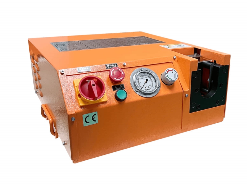
Assembly Schematic Diagram of Manual Ferrule Pre-assembly Machine KC-A02
Assembly Schematic Diagram of Manual Ferrule Pre-assembly Machine KC-A02
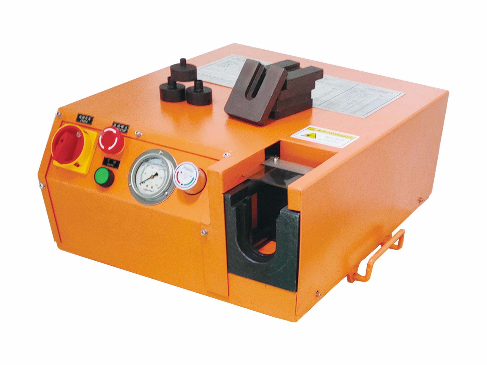
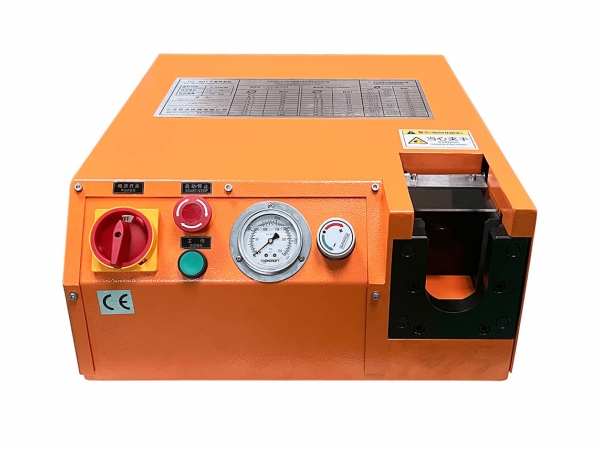
1.Before starting the pre-assembly, loosen theoil tank cover of the hydraulic pump to theventilation position first.

2.Open the safety lock.

3.Close the pressure relief valve of the manualpump.

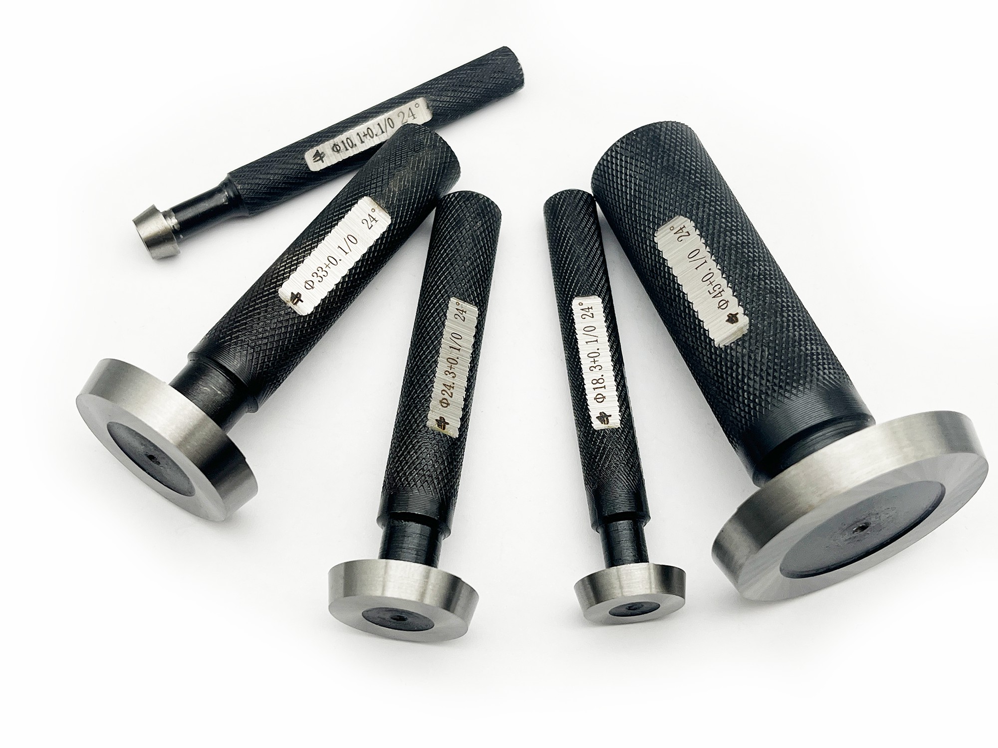
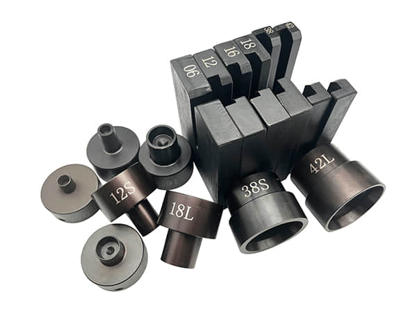
4.Install the corresponding mold on the ma-chine, insert the pin and fix the sleeve.

5.Insert the nut and ferrule into the steel pipein sequence, then put the steel pipe into themachine. Grasp the steel pipe firmly andpush it forward to the bottom of the mold.

6.Check and remember the correspondingpressure for the pipe diameter to be crimpedin the pressure reference table on the ma-chine.

7.Press the manual pump and keep an eye onthe pressure indicated on the pressuregauge. Release the manual pump until thepressure reaches the corresponding value inthe pressure reference table.

8.Open the pressure relief valve, take out thesteel pipe, and check the pre-assembly con-dition of the ferrule (it is allowed for the fer-rule to rotate left and right on the pipe).

9.After using the machine, remember to closethe oil tank cover to prevent the hydraulic oilfrom leaking.