Welcome to Ningbo Kumsung Machinery Co., Ltd.
Pre-Assembly Flaring Machine Guide: Operation, Tube Prep & Pressure Settings
Practical guidance for technicians, production engineers, and procurement teams from Ningbo Kumsung Machinery Co., Ltd.
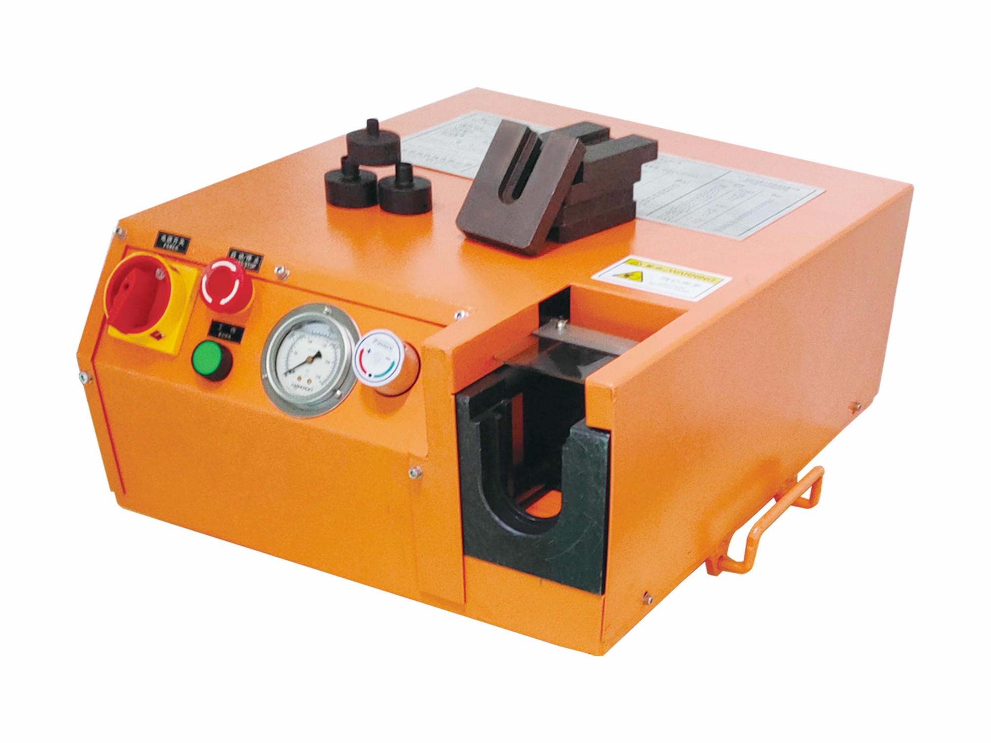
A pre-assembly flaring machine is a specialized tool used to form, preset, or flare tube ends and ferrules prior to final assembly. Proper use of this equipment increases seal reliability, reduces rework, and shortens assembly time. This guide covers step-by-step operation, how to prepare tubes and fittings before pre-assembly or flaring, what tube sizes and materials are compatible, and how to set correct pressure, preload, and flaring parameters. Practical tips and troubleshooting advice are included so your team gains consistent, high-quality results.
1. How to Use a Pre-Assembly Flaring Machine: Step-by-Step Guide
Using a pre-assembly flaring machine properly requires preparation, correct tooling, and repeatable process controls. The steps below are suitable for most industrial pre-assembly and flaring machines (hydraulic, electric, or electro-hydraulic).
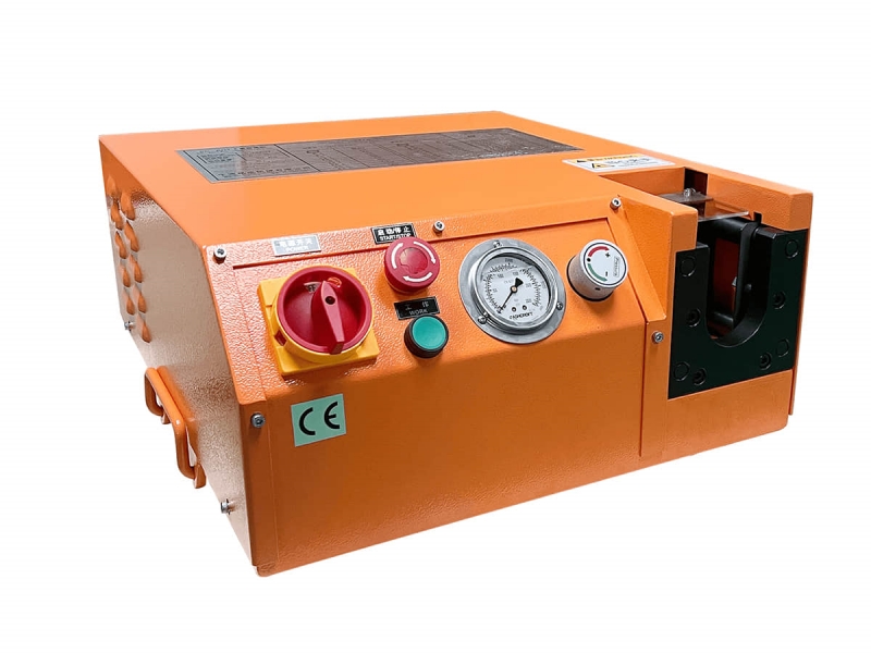
1.1 Prepare the workstation and safety checks
Ensure the machine is bolted or clamped to a stable bench or floor plate to eliminate movement.
Check hydraulic oil level and system for leaks if using a hydraulic model.
Verify electrical connections and emergency stop function for electric units.
Confirm all guards are in place and that operators wear appropriate PPE (safety glasses, gloves).
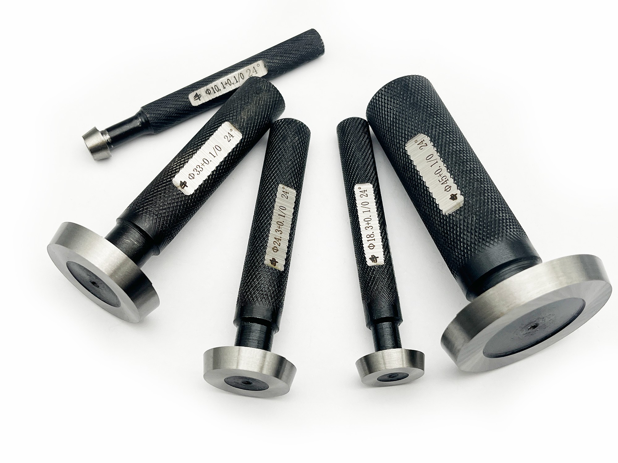
1.2 Select and install the correct die or mandrel
Dies, mandrels, and fixtures must match the tube outer diameter (OD), wall thickness, and ferrule style. Use manufacturer's die charts to select the proper tooling and install it securely. Improper tooling leads to misalignment, poor flare geometry, and premature tool wear.
1.3 Position the tube and fittings
Insert the tube to the defined stop depth; consistent insertion depth ensures repeatable flares.
Slide on nut and ferrule in the correct sequence and orientation.
Use insertion marks for batch production to reduce variability.
1.4 Set tool parameters and preload
Set the machine's preload (initial compression) and main forming stroke according to the tooling chart and material. If your machine has a digital controller, input the recommended preload, hold time, and stroke depth. If it uses an analog gauge, set the pressure regulator to the target value and verify with a calibrated gauge.
1.5 Run the pre-assembly cycle
Start the cycle and watch for smooth motion and steady pressure rise.
Hold at final forming pressure for the recommended dwell time to allow material flow and elastic relaxation.
Release pressure slowly to avoid spring-back effects and remove the workpiece.
1.6 Inspect and verify
Check visually and dimensionally that the flare geometry and ferrule seating meet specifications. For critical assemblies, perform a pressure leak test or hardness/geometry inspection on sample pieces before full production.
Pro tip: Maintain a short log for the first runs of a new setup: tooling used, pressure set, dwell time, and inspection results. This baseline speeds up troubleshooting and future changeovers.
2. How to Prepare Tubes and Fittings Before Pre-Assembly or Flaring
Preparing tubes and fittings correctly is essential—incorrect prep is a primary cause of assembly failures. Below is a checklist you can standardize in incoming inspection and production prep areas.
2.1 Cutting and squaring the tube
Use a high-quality tube cutter or saw to produce square ends. The tube end face must be perpendicular to its axis; angled or ragged cuts cause poor ferrule seating. For batch work, jigs and stops guarantee consistent cut lengths and squared ends.
2.2 Deburring and chamfering
Deburr the internal and external edges after cutting to remove sharp metal chips.
Apply a small chamfer (as recommended by fitting specifications) to prevent burrs from damaging ferrules.
2.3 Cleaning and contamination control
Remove oil, grease, dust, and metal particles. Use lint-free wipes, solvent cleaning, compressed air, or ultrasonic cleaning for high-precision systems. Contaminants can impede ferrule bite and cause leakage in high pressure systems.
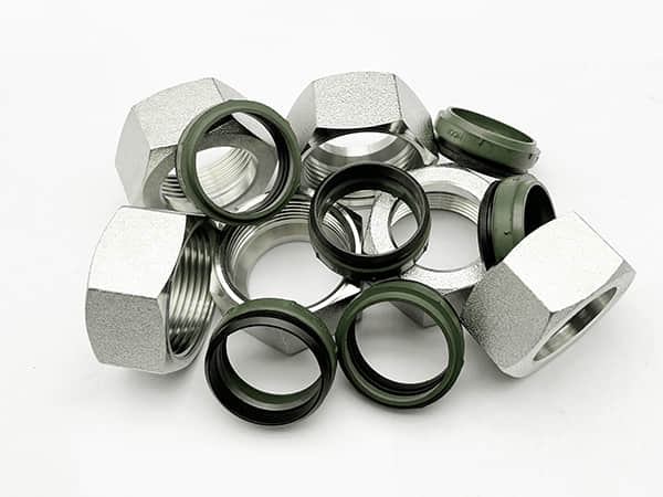
2.4 Inspect fittings and ferrules
Check ferrules and nuts for burrs, deformities, or surface defects. Use only matching ferrules designed for the chosen fittings—mixing brands or types can alter deformation characteristics and reduce sealing performance.
2.5 Pre-assembly staging
Stage components in size-coded bins, tag batches with lot numbers and tooling used. For traceability in critical industries (aerospace, rail), keep a record of parts and parameter sets used for each production run.
3. What Tube Sizes and Materials Are Compatible with Pre-Assembly Flaring Machines
Compatibility depends on the machine's design and the tooling available. Understanding the limits and material behavior ensures safe operation and repeatable results.
3.1 Typical tube diameter ranges
Machines commonly accommodate a band of diameters, e.g. from small precision ODs (3–6 mm) up to medium or large ODs (e.g. 25–50 mm), depending on model. Always consult your machine's technical sheet for exact capacity. If your production needs cover a range outside standard tooling, inquire about interchangeable die sets or custom tooling.
3.2 Wall thickness and strength considerations
Wall thickness affects the forming force required and the risk of cracking. Thin-wall tubes need gentler forming profiles and controlled hold times, whereas thick-wall tubes require greater force and a robust machine frame. The machine stroke and force rating must match the maximum wall thickness you intend to process.
3.3 Material types and forming behavior
Carbon steel: Common in industrial systems; predictable forming but surface rust must be controlled.
Stainless steel: Higher strength and hardness—requires higher forming force and may need special dies to prevent galling.
Low alloy steels: Behavior varies; follow supplier’s forming data.
Copper or brass: Softer and easier to form but care must be taken to avoid over-compression and deformation.
3.4 Special applications and exotic alloys
For aerospace or corrosive environments, titanium or nickel alloys may be used. These materials often require specific tooling and process development; consult the machine vendor and material supplier for forming recommendations.
3.5 Standards and interchangeability
Many hydraulic fittings follow DIN, ISO, or SAE standards. Ensure ferrules, nuts, and fittings match the standard required by your system. Using non-standard components risks improper sealing and can be a safety hazard.
4. How to Set the Correct Pressure / Preload / Flaring Parameters
Correct pressure and forming parameters are the foundation of a reliable pre-assembly process. Below are practical steps to determine and validate those parameters.
4.1 Understand the difference: preload vs. forming pressure
Preload (or initial compression) stabilizes the assembly and prevents slipping; forming pressure is the peak force that produces the final flare or ferrule deformation. Both must be controlled and repeatable.
4.2 Use manufacturer data and material charts
Start with pressure and stroke values from the fitting/ferrule manufacturer and your tooling supplier. These charts give recommended pressures for specific tube OD, wall thickness, and material. Treat them as the starting point for your machine setup.
4.3 Calibrate with test samples
Run test pieces at the recommended parameters.
Inspect geometry, measure critical dimensions, and perform leak checks.
Adjust pressure, dwell time, or stroke incrementally as needed.
4.4 Parameter examples (illustrative — validate for your system)
Note: The numbers below are illustrative. Always follow official manufacturer guidance and validate on test parts.
Small stainless tube (6 mm OD, 1.0 mm wall): higher forming pressure, shorter dwell (e.g., starting at X MPa, validate with test piece).
Carbon steel tube (12 mm OD, 1.5 mm wall): moderate forming pressure, standard dwell.
Large diameter (25 mm OD): greater force and longer dwell to allow metal flow.
4.5 Monitoring and quality control
Install monitoring systems where feasible—pressure transducers, cycle counters, and torque/force logging. Sample parts from each batch should be inspected, and process logs retained to demonstrate conformance for critical systems.
4.6 Troubleshooting common parameter issues
Insufficient pressure: ferrule does not bite, leaks during pressure testing.
Excessive pressure: tube deformation, cracks, or ferrule over-compression.
Uneven flares: tooling misalignment, wrong die, or tube not inserted to stop depth.
5. Best Practices, Maintenance and Process Stability
5.1 Routine maintenance
Inspect and replace hydraulic seals and hoses annually or per hours of operation.
Change hydraulic oil at recommended intervals to prevent contamination and valve wear.
Keep dies and mandrels clean and free from nicks; re-grind or replace worn tooling.
5.2 Operator training & standard work
Develop standard operating procedures (SOPs) and train operators on insertion depth, parameter entry, inspection criteria, and basic troubleshooting. Well-trained operators reduce variability and scrap.
5.3 Traceability and continuous improvement
Log tooling used, parameter sets, operator ID, and inspection results. Analyze scrap trends and drive continuous improvements to tooling, parameters, and material procurement.
6. Common Questions and Quick Answers (FAQ style)
Q: Can I use the same machine for different tube materials?
A: Yes—if the machine has the force capacity and you change dies and adjust parameters for each material. Always validate by testing.
Q: How often should I calibrate the pressure gauge?
A: Calibrate pressure gauges and transducers annually or if you observe drift in assembly results.
Q: What is the main cause of leaks after pre-assembly?
A: Most leaks stem from incorrect insertion depth, contaminated surfaces, or incorrect pressure settings. Reinspect all three when troubleshooting.
7. Why Invest in a Quality Pre-Assembly Flaring Machine?
Reliable equipment yields fewer leaks, less rework, faster output, and improved safety—benefits that rapidly offset initial investment. In regulated or safety-critical industries, traceable, repeatable pre-assembly processes are often mandatory.
8. About Ningbo Kumsung Machinery Co., Ltd. — Your Partner in Hydraulic Connection Solutions
Ningbo Kumsung Machinery Co., Ltd. specializes in ferrule pre-assembly machines and hydraulic pipeline connection components, including EO-2 functional nuts, connectors, and ferrules. Our equipment is used across road transportation, aerospace, marine, rail transit, and industrial machinery sectors.
Our Ningbo facility continuously upgrades product design and develops new equipment to meet evolving customer needs. Kumsung pre-assembly machines have proven to improve pre-assembly stability, reduce pre-assembly time, and increase production efficiency while guaranteeing assembly quality.
We operate under the principle that quality is the life of an enterprise. Our aim is to win recognition through excellent products and responsive service. Ningbo Kumsung is committed to delivering efficient, reliable hydraulic connection solutions to domestic and international customers.
9. Take Action — Improve Your Hydraulic Assembly Quality Today
Ready to lower leak rates, increase throughput, and standardize your hydraulic assembly process? Contact Ningbo Kumsung Machinery for expert consultation, machine selection assistance, and customized tooling solutions. Our technical team can help you choose the correct model, set up parameters, and develop SOPs tailored to your production.
Contact Ningbo Kumsung Machinery — Request a Quote & Technical Consultation