Welcome to Ningbo Kumsung Machinery Co., Ltd.
Assembly Schematic Diagram of the Memory Pipe Bending Machine
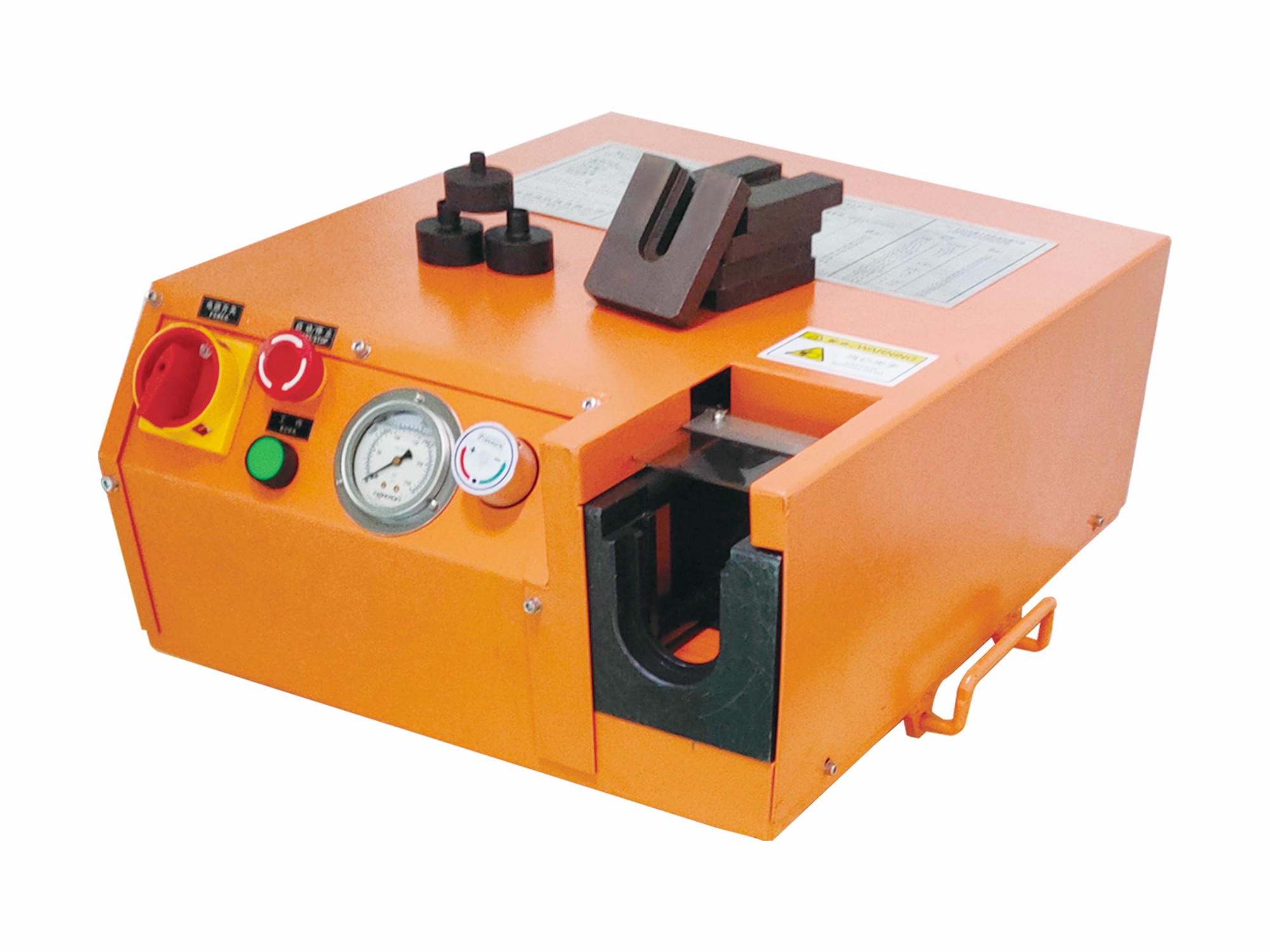
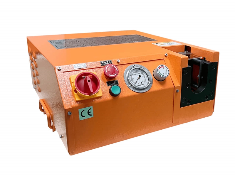
The KC-K01 device is an electro-hydraulic controlled pipe bender, a compact and mobile numerical control equipment. It is mainly used to push and bend metal pipes or solid metal round bars into the required shapes. It can perform pushing and bending at multiple angles, and the angles can be memorized and saved. It can repeat the previously bent angles. The specially designed molds, in coordination with the servo control, can ensure that the pipeline will not be flattened or suffer other similar issues during the bending process.
Supported materials for pushing and bending: carbon steel pipes, copper pipes, stainless steel pipes, solid round bars according to the pipe diameter, etc. The pushing and bending diameter range is: 6-42mm.
Assembly and Operation Steps
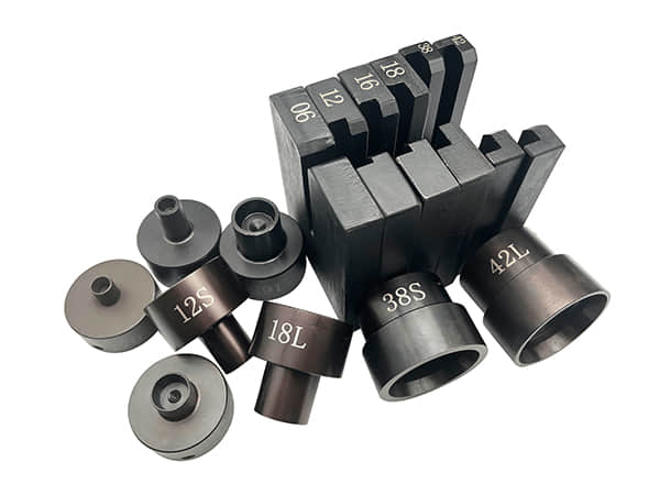
Install the integrated pushing die. After aligning it to the position, tighten and fix it with screws, and also tighten the screws on both sides.

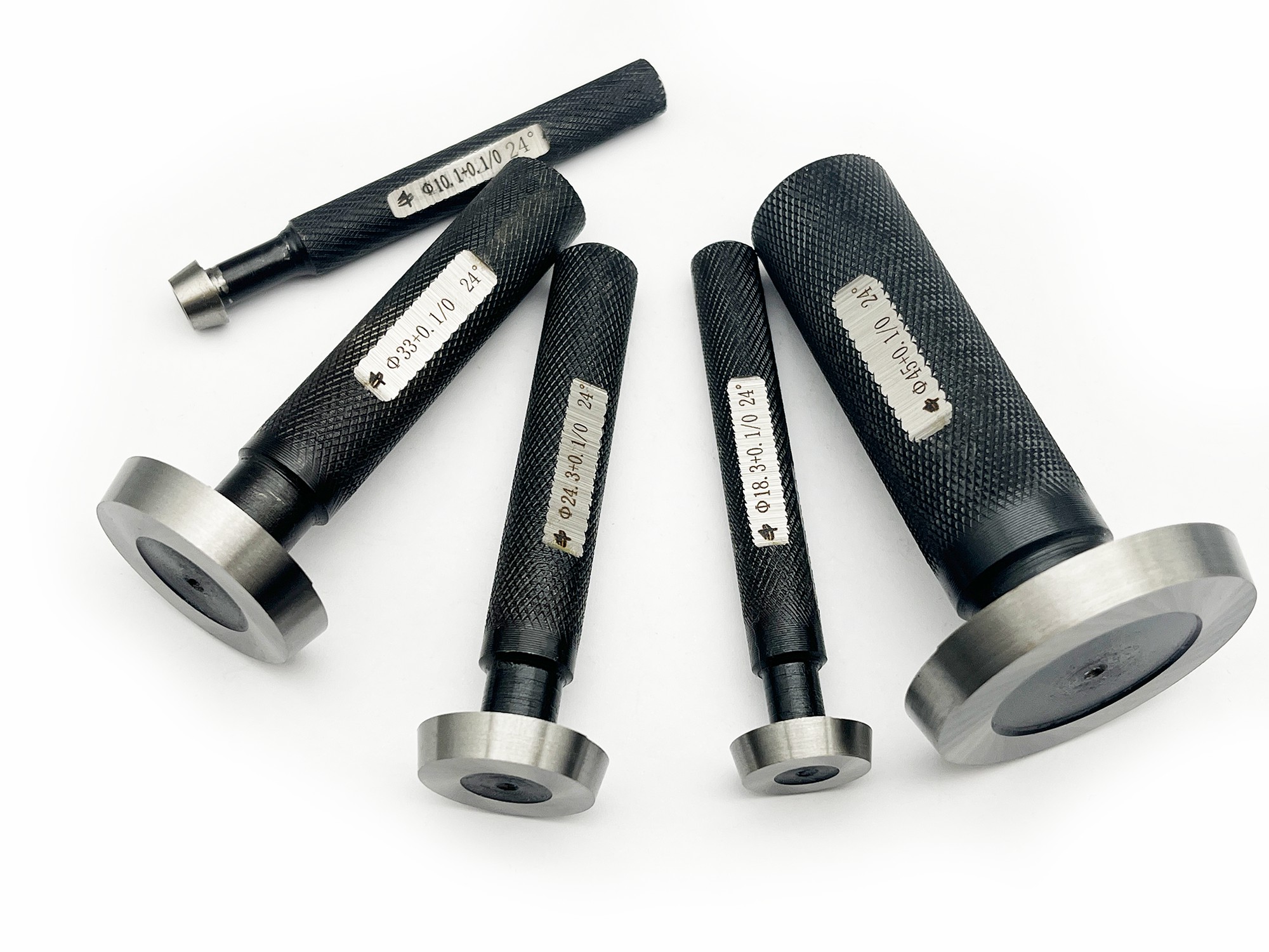
Select the appropriate profile mold and clamping mold according to the diameter of the pipe and install them.

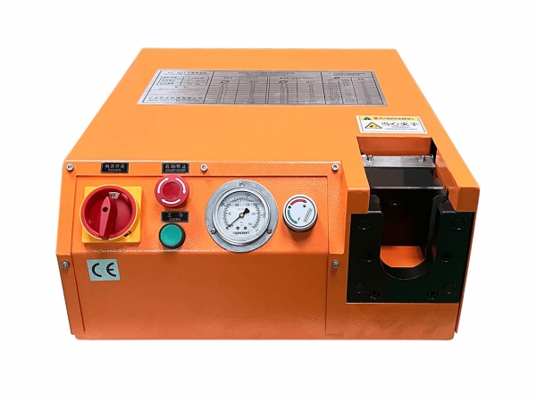
After connecting the machine to the power supply, turn on the power switch.

Place the steel pipe properly and step on the left foot pedal until the pipe is tightly pressed.

Tap the foot pedal until the pipe is bent to the desired angle.

After the angle is bent properly, step on the right pedal to retract and push the mold, take out the steel pipe, and then the pipe bending is completed.

Memory angle: After the device is powered on, first adjust the channel from "0" to "1", and then step on the pedal to bend a pipe.

Press the memory button to turn it on. At this time, the angle has been memorized in channel "1". Then, step on the right foot pedal to retract the pushing die.

Angle compensation:

Place the steel pipe that has just been bent properly on the pipe bender, step on the left foot pedal, and the machine will automatically push the steel.
Check the condition of the steel pipe. If the steel pipe is loose, it indicates that the angle is too small, and you need to click the "+" button for compensation.
If the steel pipe is too tight, it indicates that the angle is too large, and you need to click the "-" button for compensation.
After the memory compensation, step on the right foot pedal to retract the pushing die to an appropriate position, and the angle memorization is completed.
Test the memorized angle:

Take a new steel pipe and place it at the corresponding position of the pipe bender.
Step on the left foot pedal. If the pushing die automatically pushes to the angle memorized in Channel "1", it means the angle memorization is successful.
Multi-memory pipe bender: After tuning to another channel (press and turn off the memory button), repeat the above operation to store other angles. Angles can be stored for channels 1 to 9.